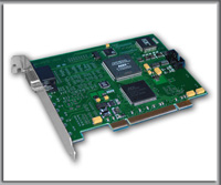
| HSD-NCO V200 |
| Universal Generator / Counter |
 |
|
| The HSD-NCO V200 is a PCI card developed for pulse generation and frequency measurement: |
 |
Numerically Controlled Sinus Oscillator 0.005 Hz - 100 kHz. |
|
|
 |
Additional TTL Generator 0.1 Hz - 1 MHz. |
|
|
 |
Universal Counter with two inputs |
|
|
| The NCO card uses Analog Devices AD7008 chip to give you digitally created sine waves. |
| The universal counter can function as a Frequency Counter, Period Counter, Frequency Ratio (fa/fb) Counter, Time Interval Counter and a Totalizing Counter. For period and time interval, the 40 MHz timebase gives 25 ns resolution. In the frequency mode, the user can select accumulation time of 100 ms, 1 s, 10 s and 100 s. With a 100 s accumulation time, the frequency can be displayed to a resolution of 0.01 Hz. |
| Numerically Controlled Sinus Generator 1 |
| Specification: |
 |
Frequency range: 0.005 Hz - 100 kHz |
|
|
 |
Sine wave output amplitude Vpp: 0.8 V to 4.0 V |
|
|
 |
Sine wave output offset: +/-1.0 V |
|
|
 |
Maximum output current: 50 mA |
|
|
| TTL Generator 2 |
| Specification: |
 |
Frequency range: 0.1 Hz - 1 MHz |
|
|
| The TTL Output BNC Connector can be supply by Generator 1 or Generator 2 (software select). |
| Universal Counter |
| The Univerasal Counter has two inputs: Input A and Input B. Generator outputs can be also internally conected to the counter. There is a possibitity to choose an active input slope. The gate time for High Frequency Mode can be select from 0,1 s to 100 s.
Universal counter working modes:
|
 |
High Frequencies In this mode input pulses are accumulated by the time of 100 ms, 1 s, 10 s or 100 s. Input can be selected as Input A, Input B, Generator 1 or Generator2. |
|
|
 |
Low Frequencies In this mode the 40 MHz clock is accumulated by the input pulse period. Input can be selected as Input A, Input B, Generator 1 or Generator2. |
|
|
 |
Frequency Ratio A/B or B/A In this mode the frequency ratio between inputs Input A and Input B (or Input B and Input A) is measured. Displayed value has no unit. |
|
|
 |
Time Interval In this mode the time interval between the pulse in Input A and the pulse in Input B is measured. Displayed unit is seconds. |
|
|
 |
Manual In this mode the time interval between pressing the START and the STOP button is measured. Displayed unit is seconds. |
|
|
 |
Counter In this mode pulses from Input A are accumulated by the given time. |
|
|
 |
Calibration In this mode pulses of 40 MHz are accumulated in the time of 100ms, 1s 10s or 100s. |
|
|
| The value can be displayed as: |
 |
Frequency (Hz or kHz) |
|
|
 |
Period (s) |
|
|
 |
Rotation per minute (kR/min or R/min) |
|
|
|
| |
|
|
|
 |
Select
from list: |
|
|
 |
Applications |
|
|
| The HSD-NCO V200 can be used in applications where precise and highly stable sine wave and TTL pulse generation is required. |
|
|
|
 |
Inputs and outputs |
 |
Four BNC connectors are used for main signals: |
 |
Sinus Generator Output is the analog output of the sinus wave |
 |
TTL Output is the TTL output of Generator 1 or Generator 2 (software select) |
 |
Input A is the first input of Universal Counter |
 |
Input A is the first input of Universal Counter |
 |
Input B is the second input of Universal Counter |
|
|
|
 |
Software |
 |
Control software for Windows 98/2000/XP. |
|
|
|
|