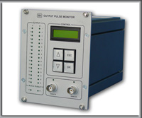
| HSD-MUX-V10-PD Multiplexer Module |
| HSD-MUX-V10-PD Multiplexer Module |
 |
The multiplexer HSD-MUX-V10-PD is an EURO module developed for switching sequencers outputs.
Two standard Sequencer V5.1 euro modules and the HSD-MUX-V10-PD multiplexer module are used to control PIV (Particle Image Velocimetry) measurement systems.
|
|
|
| HSD-MUX-V10-PD multiplexer module is composed of six functional blocks: |
|
 |
Sixteen-bit multiplexer block,
which switches sequencers outputs. The multiplexer has sixteen TTL input
parts allotted for A-Sequencer, sixteen TTL input parts allotted for B-Sequencer,
and sixteen TTL output parts. |
|
|
 |
Additional four-bit
multiplexer block, to be freely applied by the user. The multiplexer
has four TTL A inputs, four TTL B inputs and four TTL outputs. |
|
|
 |
Trigger block, two
inputs Select A and Select B, and multiplexers control circuit. |
|
|
 |
Output pulse display
of 32 LEDs. |
|
|
 |
Output drivers block.
Herewith the voltage of each of the sixteen-bit multiplexer signals
can be set to TTL standard, or higher according to the requirements
of the external equipment connected to the sequencer outputs. |
|
|
 |
Keyboard and LCD display. |
|
|
|
|
|
 |
Select
from list: |
|
|
 |
Principle of operation |
|
|
Sixteen-bit multiplexer and four-bit multiplexer are switched by one pulse generated by triggers block.
Rising or falling Select A pulse edge sets the multiplexer so that pulses from Sequencer A appear at its outputs. Simultaneously, it switches the user multiplexer block.
Rising or falling Select B pulse edge sets the multiplexer so that pulses from Sequencer B appear at its outputs. Simultaneously, it switches the user multiplexer block.
The high level of the Data Record pulse corresponds to the B active status. The active edge at Select A trigger input sets Data Record output to low level and switches the multiplexer so that pulses from sequencer A. occur at its outputs.
|
|
|
|
|